PROCEDURE
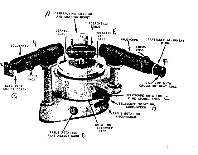
On the picture below labels the parts of the spectrometer A, B, C ...
Regarding A, for some reason the factory put the label on its side instead of along the comment applies to the "575 lines/mm" grating, but there are lots of grating around; if you wish to use another one that's fine). The picture is a little funny since it looks there like they've got the light reflecting off the grating into the telescope (F), but we want an arrangement as follows:
Now , alignment will probably take a while and use the diffused laser beam to help. Note the vernier scales; it's important that you know how to use them. We want the straight-through (diffused, for the sake of your eye) laser beam through H {"cooimator is a fency term for a simple idea; anytime you look through a tube so that you're only receiving "parallel" light, that's collimation} coming over the 180 degrees mark hitting A perfectly "normally" (at 90 degrees) and then exactly over the 0 degrees to be seen as a slit with cross-hairs on top of it in the telescope (F). How can one achieve this?
The lens sits and the lens position (where it attaches magnetically to its holder on the optical bench) are variables. Regarding the 90 degrees between the laser beam and the grating, once you've got things pretty close to perfect, swiveling the spectrometer table (note that it has a lock screw that can be loosened) back and forth should produce some optical "clues" as to when you've got it right at 90 degrees. Again, if possible, adjust the apparatus so that the cross-hairs are on the vertical slit ( make it pretty narrow; see G)of straight-through laser light directly at 0.0. Be sure you understand the function of B and C; C is very useful (especially when the slit is narrow - for best precision ) as a fine tuner (applicable only when B is locked down, but B will Have to be unlocked when you're hunting those spectral lines, later). In using the vernierm you may need a small light, and magnifying glass, and you probably already know that crazy people divide degrees into "60 minutes" of arc. Adjust the lighting of the room as you see fit.
After alignment comes calibration. I don't think we should believe what the factory specifies for the grating (recall from Phys 203/223 lab that the grating specifies the reciprocal of d, where d is distance between the "lines" (which scatter the light on A) and thus should be a little skeptical about dfactory (calculate this). You can find out what d really is (dcalibration) by using the fact that the helium-neon laser wavelength is 632.8 nm. Unlocking B, we swing F over to the first order diffraction of the laser light (I hope this term is familiar form Phys 203/223) and then lock B and use C to get the cross-hairs right on top of it and accurately measure that angle and use (form that course) the diffraction formula
Equation 1 ml=dsinq (where m=1 for "first order")
to solve for dcalibration. Compare the factory's value to this (using the usual
dfactory-dcalibration
percentage difference: ------------------------------------ X 100 % ). For the rest
dcalibration
of the lab (when getting the wavelengths for the spectral lines, use dcalibration for d equation 1. Tube (Hydrogen) in holder and rearrange things so that the thin part of tube is quite close to the slits on the collimator and to maximize the light from the tube getting into the collimator, moving F out of the way and putting your eye by the 0 degrees make ( so your looking through A and H toward the glowing tube; move the wooden platform that the spectrometer sits on back and foth until it looks as if as much light is possible is coming through those slits (but don't crank those slits wide open, since that would cost you precision in your result). Then find those spectral lines (sort of like what's in the charts on the wall). Repeat this for the Helium discharge tube (writing down all the angles and computing all the wavelength). If any of the spectra look very odd (very different form the picture on the wall, not just different in a couple of details), one problem these low-pressure tubes have is that air wants to leak in and that introduce many "spurious" lines. Other tubes certainly can be looked at (but you don't have to record any numbers) like the krypton, argon, if you wish.
Comments: One of the difficulties with this experiment (besides seeing that blasted angle well enough to read it to the nearest "minute of arc", but a magnifying glass and a flashlight can help with that) is the alignment so that the "straight-through" light really comes out at 0.0 degrees the way at should. This is so difficult, in fact, that I have since (meaning since I wrote the previous part of this lab) decided that it is much better to read the angle q for the "first-order"diffracted line on both sides and then averaging to get the "true" q . Be careful with the initial alignment step, since a slight sloppiness in true-zero gets "averaged over" in this approach.
Further Comments: The extra-tedious business of measuring the angle on both sides and then averaging (described on the previous page) does not need to be done for the helium (He) source. It should be done for the HeNe laser (which has a "known" l=632.8nm and thus serves to calibrate the grating; once "d" is determined by that experiment then that value of e done for the hydrogen (H) lines, since we want "d" is used to translate the spectral lines form the H, and He, tubes form angles into wavelengths (preferably in nanometers, "nm")). And it should bring your angles into wavelengths and then glancing at the standard values for those wavelengths are given.
